Applied Aerodynamics Laboratory
About the lab
Western Michigan University's Applied Aerodynamics Laboratory, located at the Kalamazoo International Airport, is operated by the Department of Mechanical and Aerospace Engineering.
The laboratory houses the Advanced Design Wind Tunnel, the Small Wind Tunnel (SWT), and the GM Wind Tunnel (to be set up) and a small turbine engine test cell. The Applied Aerodynamics Laboratory conducts research in measurement techniques and experimental and applied aerodynamics.
The lab has close collaborations with other WMU labs, including the following:
- Fluid Mechanics Laboratory
- Computational Fluid Dynamics Laboratory
- other related departments at WMU
Contact
Dr. Tianshu Liu, Professor
Department of Mechanical and Aerospace Engineering,
G-217, Parkview Campus,
Western Michigan University, Kalamazoo, MI 49008, USA.
Fax: (269) 276-3421
Selected research topics
- Pressure and temperature sensitive paints in aerodynamics
- Fluid flow and optical flow: general framework for global flow diagnostics
- Geometric and kinematic aspects of image-based measurements
- Global luminescent oil-film skin friction meter
- Skin friction topology in complex separated flows
- Extraction of skin friction fields from surface flow visualizations as an inverse problem
- Analytical and numerical inverse methods for determining heat flux in TSP measurements in hypersonic wind tunnels
- Videogrammetry and vision for aerospace applications
- Airfoil/wing flow control using trailing edge devices
- Aeroship: hybrid fight platform for personal, near-space and planetary flight
- Scaling analysis of propeller-driven mars aircraft
- Flapping flight: scaling, geometry, kinematics, aerodynamics, design and testing\
- Wind oscillator for power generation
- Fluid mechanics of deposition of micron droplets on wall in turbulent flows
Testing Capabilities
Western Michigan University's applied aerodynamics laboratory took over the advanced design wind tunnel from the former McDonnell Douglas Aircraft Company (now the Boeing Company at St. Louis) and had it installed at the current location since 1999. The ADWT provides the opportunity for fundamental aerodynamic studies and efficient optimization of aerodynamic configuration through the use of small scale, easily fabricated and modified wind tunnel models with very low operating costs and a minimum of operating personnel.
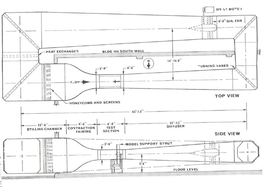
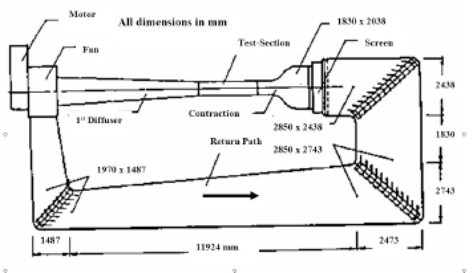
The wind tunnel is a low-speed, closed-circuit single return, atmospheric tunnel with a test section of 32 inches high, 45 inches wide, and 8 feet long (see figure 1). The 161-foot-long circuit consists of two legs of 65.6 feet long and the other two legs of 14.9 feet long. Low turbulence and good flow direction control are obtained by a combination of features including four screens and honeycomb in the stilling camber, a 10 to 1 stilling chamber to test section contraction ratio, empirically tailored test section walls, tangential flow breathing at the test section exit to the diffuser, and a 5.4 degree diffuser angle. The main drive power source is a 125 hp DC motor with a solid state SCR speed control. The 16-blade fan is 6 feet in diameter. Cooling is accomplished by passing water through a copper tube heat exchanger.
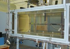
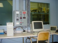
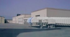
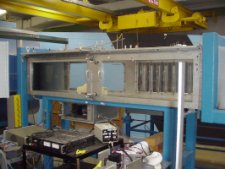
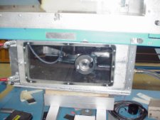
The flow velocity range is approximately 20 to 240 ft/sec (6 to 73 m/sec) where the total temperature is in the range of 60 to 120oF. This corresponds to dynamic pressures up to 65 lb/ft2 and Reynolds numbers up to 1.3 ´ 106 per foot. Depending upon air temperature and the model dimensions, testing can be extended to the 65 to 75 lb/ft2 band. Figures 2, 3 and 4 show the test section, control room and returning section of the ADTW, respectively.
Operational characteristics
- Closed circuit, atmospheric pressure, continuous flow
- Airspeed range, 20 to 240 ft/sec (dynamic pressure, q, up to 65 lb/ft2)
- Reynolds number to 1.3 ´ 106 per foot
- Turbulence factor 1.08
- Test section size, 32 by 45 in. by 8 ft long
- Full test section length Plexiglas windows on sides and ceiling for optical access
- Drive motor, 125 hp DC
Model support and traverse systems
- Parallelogram linkage sting support system
- Angle of attack range up to ± 36 degrees, setting within 0.1 degree
- Vertical translation 6 in. above to 15 in. below tunnel centerline, setting within 0.01 in
- Removable panel for floor model support
- Rotating table on the floor
- Traverse system of two degrees of freedom for probes
Applications
The ADWT is used for measurements of forces and moments, pressure fields and flow fields on and about relatively small aerodynamic models. Since operating costs are low, this facility is particularly well suited for fundamental studies of flow physics, development of new aerodynamic measurement techniques, and exploratory tests with inexpensive, easily modified models.

The small wind tunnel, with its 16-by-16 inch test section, is a low speed, open return tunnel. It is mainly used for airfoil section tests and teaching. The velocity is up to 50 m/s. The small wind tunnel is equipped with an external three-component force balance. PC is used for tunnel control and data acquisition.
Other facilities include a small probe calibration tunnel and a smoke visualization tunnel.
The basic research wind tunnel at Western Michigan University's applied aerodynamics laboratory is shown schematically in Figure 1. It was donated by General Motors. This tunnel will be set up as long as the lab space is available. It is particularly suitable for ground vehicle testing.
This is a closed-circuit, closed test section wind tunnel with a rectangular test section that is 711 mm wide and 507 mm high at the entry. The test section is 2285 mm long and the side walls have a small divergence angle of 0.35 degrees to account for the growth of the wall boundary layers. The tunnel in its present configuration has a contraction ratio of 10.67.
Immediately upstream of the contraction, a flow straightener and two wire-mesh anti-turbulence screens are installed. The return path is of the diffuser type and the corners were constructed to be diffusion free. The turning vanes were made of circular arc sections with straight trailing-edge extension. A Westinghouse Class III 1370 mm centrifugal-type fan with a side discharge is used to create the air flow. The fan is driven by a 18 kW Reliance Max Pak DC variable-speed motor which is controlled by a potentiometer. The test section is equipped with a six-component strain gauge balance unit by Microcraft, Inc.
Image-based aerodynamic measurement techniques are being developed at Western Michigan University's applied aerodynamics laboratory under a unified theoretical framework to provide integrated three-dimensional, quantitative optical diagnostics of different aspects of complex flows on and around an object (e.g. aircraft model), and gain a deeper and more complete understanding to related physical phenomena. In particular, the theoretical foundation for unified flow vector field diagnostics is the physics-based optical flow method.
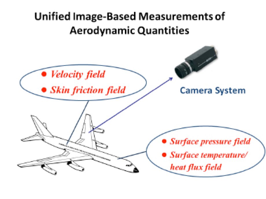
These image-based techniques include pressure and temperature sensitive paints (PSP and TSP), stereoscopic particle image velocimetry (SPIV), continuous scalar velocimetry (CSV), planar laser induced fluorescence (PLIF) system, optical skin friction meters, high-speed videogrammetric system for kinematical and geometrical measurements. The unified image-based aerodynamic measurement techniques allow extractions of various physical quantities of aerodynamic flows from flow visualizations, including the fields of surface pressure, surface temperature/heat-flux, skin friction, velocity, species concentration, model deformation, and model attitude. Figure 1 illustrates the concept of the unified image-based measurements.
Several topics being studied are briefly described below.
- Pressure and temperature sensitive paints
- Physics-based optical flow method for extraction of velocity fields from flow visualization images,
- Global skin-friction diagnostics based on surface flow visualizations with luminescent oil, sublimation coating, and temperature and pressure sensitive paints.
- Photogrammetry/videogrammetry for measurements of static and dynamic model deformation and attitudes and optical force measurements.
- Other relevant topics including skin-friction topology, avian wing geometry and kinematics, comparative scaling of fixed and flapping flyers, wing flow control, and oil droplet deposition in turbulent flow.
Force measurement equipment
AEROLAB sting balance
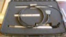
The six-component internal force balance (AEROLAB) is available for aerodynamic force measurement (as shown In Fig. 2), which has the measurement ranges described in the following table.
Normal Force (Lbs) 50 to 200 | Pitching Moment (In.-Lbs) 75 to 300 | Side Force (Lbs) 30 to 200 |
Yawing Moment (In. Lbs) 37.5 to 250 | Rolling Moment (In.-Lbs) 15 to 100 | Axial Force (Lbs) 25 to 50 |
Western Michigan University's Applied Aerodynamics Laboratory is equipped with a JR3 balance (UFS-45A50-ITI) capable of measuring two components of force (drag and lift) with a standard maximum range of ± 50 lb with a digital resolution of 0.013 lb in each direction. The nominal accuracy of the balance is of ± 0.25 % of the measuring range, which translates on a nominal accuracy of ± 0.125 lb.
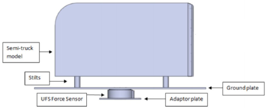

The model currently tested is connected to the balance is by having the ground plate bolted to the balance and then the semi-truck model attached to the ground plate through a set of four stilts, as represented in Fig. 1. Thus for the testing of another model it is recommended to build the model along with the ground plate. The ground plate will need to have six through holes that match the balance threaded holes shown in the top view of the balance in Fig. 2. The through holes that attach the ground plate to the balance must have a diameter of 7 mm and must be placed on a 59 mm diameter circle as shown in the previous figure. The holes are equally spaced (60o apart). Finally, the balance has a diameter of 101 mm.
Fax: (269) 276-3421